Lab Computational Electromagnetic Channel Simulation for Smart Antenna / MIMO Systems
In this project, DWSL addresses the problem of near-field and far-field propagation by combining two different computational electromagnetic (CEM) techniques: Method of Moments (MoM) and Electromagnetic Ray Tracing (ERT).
Next-generation communications systems will make use of smart antenna technology to handle the increasing demand for wireless services. Smart antenna technology makes use of adaptive antenna arrays at the basestation to improve system capacity and quality. The channel encountered by this array of antennas is referred to as the vector channel. During transmission, the excitation currents fed to the array elements are adjusted in relative amplitude and phase so as to adjust the overall radiation pattern of the array. Using these relative amplitude and phase excitations, referred to as beamforming, regions of constructive interference can be steered to focus signal energy to locations of interest. In an analogous way, by analyzing the relative amplitude and phase of signals received by the array, the direction of arrivals of incident energy to the array can be determined. This process is referred to as direction of arrival (DOA) analysis.
When smart antenna arrays are used at both ends of the communication link, the result is a Multiple-Input, Multiple-Output (MIMO) system. MIMO systems use sophisticated space-time coding techniques to greatly improve the capacity of wireless links over conventional wireless systems. The system can thus take full advantage of the spatial dimension of the propagation channel. When properly designed, these MIMO or multi-array links can provide multi-fold increases in link throughput while also providing dramatic reductions in channel variation.
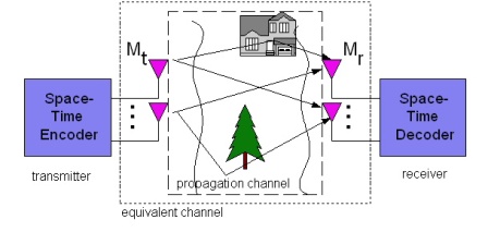
Characterizing the performance of smart antenna and MIMO systems requires understanding the complex relationship between the propagation channel and array-based signaling techniques. Unfortunately, this relationship cannot be easily quantified using simplistic approximations generally assumed by the signal processing and communication communities. Complications arise from both near-field and far-field propagation effects. Near-field effects include mutual coupling effects from one antenna array element to the others. Far-field propagation effects include the effect of the mobile environment on the multipath signal environment encountered by the array(s).
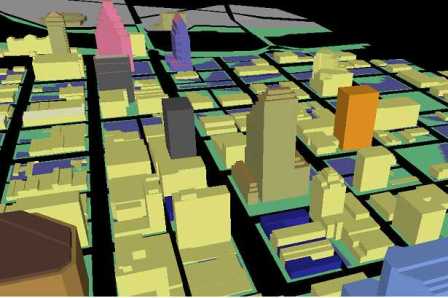
DWSL addresses the problem of near-field and far-field propagation by combining two different computational electromagnetic (CEM) techniques. These techniques are the Method of Moments (MoM) and Electromagnetic Ray Tracing (ERT) ERT makes use of a high-frequency approximation to Maxwell’s equations that considers traveling signal radiation to be directed rays. This geometrical optics approximation is used to model reflection ray mechanisms while the uniform theory of diffraction is used to consider diffraction effects. ERT simulations require computer models of the signal propagation environment of interest to be specified in terms of a computer-aided design (CAD) model. DWSL has access to CAD models of several different environments (shown below) corresponding to Philadelphia, Pennsylvania, Austin, Texas, urban training ranges at Ft. Benning, Georgia, as well as a library of generic urban environments. These environments are particularly important since next generation smart antenna and MIMO systems will likely first be deployed in dense “urban-canyon” environments. The computational effort associated with CEM simulations increases dramatically with increased geometrical complexity, with simulations sometimes requiring days or weeks.

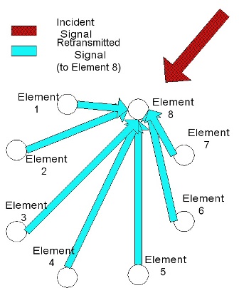
While some studies make use of ERT to study MIMO and smart antenna systems, many of those studies do not additional consider near-field mutual coupling effects. Mutual coupling effects have been shown in the past to have an appreciable effect on smart antenna system performance. They are especially important in applications in which the array elements are spaced relatively closely to one another (on the order of 1 wavelength). Mutual coupling and local scattering effects (due to antenna array mounting structure) can be accounted for using the Method of Moments (MoM). MoM uses wire modeling of antennas and the local scattering environment. Specifically, these wires are discretized into small segments. At each one of these segments, Maxwell’s boundary conditions are enforced. By enforcing these boundary conditions, the induced current on the wire segments can be expressed in terms of a given set of basis functions.
In this manner, the near-field interaction among the array elements is accurately modeled by the rigorous MoM simulation, while the far-field interaction between the array and its environment is efficiently modeled by the approximate ray-tracing solution.